Check online inventory of Stainless Steel 310 Flanges, Grade F310 Blind Flanges Dimension, SS DIN 1.4841 Forged Flanges, ASTM A182 Gr F310 Lap Joint Flanges, SS UNS S31000 Spectacle Blind Flange Exporter in India.
Stainless Steel 310 flange Specification
Specification: ASTM A182, ASME SA182
Size: 1/2" (15 NB) to 48" (1200NB)
Schedule: SCH10, SCH 40, SCH 80, SCH 160 To SCH XXS
Dimension Standard: ANSI/ASME B16.5, B 16.47 Series A & B,
B16.48, BS4504, BS 10, EN-1092, DIN, etc.
Type: Ring Joint Flange (RTJ), Flat Face Flange (FF),
Raised Face Flange (RF), Male and Female Flange (M & F),
Lap Joint Flange, Large and Small Tongue-and-Groove Flange (T & G)
Pressure rating: 150#, 300#, 600#, 900#, 1500#, 2500#,
PN6, PN10, PN16, PN25, PN40, PN64 etc.
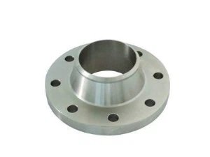
Stainless Steel 310 is well-known for its ability to endure severe heat and is thus often employed in many industries. Its superior qualities make it the preferred material for producing flanges requiring longevity and defence against corrosion in severe conditions. Stainless Steel 310 flanges display impressive capability in extremely hot temperatures, making them suitable for use in furnace components, heat treatment baskets, and kiln liners.
The oxidation resistance is one of the major characteristics of stainless steel 310 flanges. Chromium (25-28%) and Nickel (19-22%) are in abundant quantities in this grade which helps create an oxide layer on the surface of the flanges. This layer acts as a shield to guard against oxidation and prevents the flanges from being corroded in hostile and extreme temperatures. Furthermore, the high chromium content adds to its resistance to sulfidation and other forms of high-temperature corrosion.
An important attribute of Stainless Steel 310 flanges is their sturdiness and robustness. The composite of elements, including manganese, silicon, and carbon, reinforces the material's mechanical attributes, allowing it to be used in situations that require it to manage heavy weight and resistance. The large nickel concentration in Stainless Steel 310 also increases its malleability, making it simpler to form and join together.
The key component of Stainless Steel 310 grade is iron, backed up by alloying elements that offer special characteristics. Chromium boosts corrosion resistance, and nickel heightens the grade's resistance to heat, acids, and alkalis. Manganese boosts the strength and solidity of this grade, while silicon helps with oxidation resistance. Carbon can be controlled in amount for improved hardness and greater resistance to deformation.
Stainless Steel 310 flanges Specifications
| Specifications | ASTM A182, ASME SA182 |
|---|---|
| Size | 1/2″ to 48″ |
| Standards | ANSI Flanges, ASME Flanges, BS Flanges, DIN Flanges, EN Flanges, etc. |
| Dimensions | ANSI/ASME B16.5, B 16.47 Series A & B, B16.48, BS4504, BS 10, EN-1092, DIN, etc. |
| Pressure Ratings | Class 400, Class 150, Class 1500, Class 300, Class 900, Class 2500, Class 600 |
| Flange Face Type | Flate Face, Raised Face, Ring Type Joint |
| Coating/Surface Treatment | Yellow Transparent, Oil Black Paint, Anti-rust Paint, Cold and Hot Dip Galvanized, Zinc Plated. |
At our company, we take great care in packaging Stainless Steel 310 flanges to ensure their safe delivery and protection. We understand the importance of preserving the quality of the product during transit. Therefore, we utilise sturdy and durable packaging materials that provide adequate cushioning and support.
Each flange is individually wrapped and securely placed in boxes or crates, minimising the risk of damage or scratches. Our meticulous packaging process guarantees that the Stainless Steel 310 flanges reach our customers in excellent condition, ready for immediate use.
A182 F310 Threaded Flange Sizes And Schedules
| Nominal Pipe Size | Outside Diameter of Flange | Thickness of Flange | Diameter of Raised Face | Diameter of Hub at Base | Length Thru Hub | Diameter or Bore | Diameter of Hub at Bevel | Radius of Fillet | Depth of Socket | |||
|---|---|---|---|---|---|---|---|---|---|---|---|---|
| Welding Neck | Slip-On Threaded Socket | Lap Joint | Slip-on Socket | Lap Joint | ||||||||
| O | Q | R | X | Y | Y | Y | W | B | H | r | Z | |
| 1/2 | 3-1/2 | 7/16 | 1-3/8 | 1-3/16 | 1-7/8 | 5/8 | 5/8 | .88 | .90 | .84 | 1/8 | 3/8 |
| 3/4 | 3-7/8 | 1/2 | 1-11/16 | 1-1/2 | 2-1/16 | 5/8 | 5/8 | 1.09 | 1.11 | 1.05 | 1/8 | 7/16 |
| 1 | 4-1/4 | 9/16 | 2 | 1-15/16 | 2-3/16 | 11/16 | 11/16 | 1.36 | 1.38 | 1.32 | 1/8 | 1/2 |
| 1-1/4 | 4-5/8 | 5/8 | 2-1/2 | 2-5/16 | 2-1/4 | 13/16 | 13/16 | 1.70 | 1.72 | 1.66 | 3/16 | 9/16 |
| 1-1/2 | 5 | 11/16 | 2-7/8 | 2-9/16 | 2-7/16 | 7/8 | 7/8 | 1.95 | 1.97 | 1.90 | 1/4 | 5/8 |
| 2 | 6 | 3/4 | 3-5/8 | 3-1/16 | 2-1/2 | 1 | 1 | 2.44 | 2.46 | 2.38 | 5/16 | 11/16 |
| 2-1/2 | 7 | 7/8 | 4-1/8 | 3-9/16 | 2-3/4 | 1-1/8 | 1-1/8 | 2.94 | 2.97 | 2.88 | 5/16 | 3/4 |
| 3 | 7-1/2 | 15/16 | 5 | 4-1/4 | 2-3/4 | 1-3/16 | 1-3/16 | 3.57 | 3.60 | 3.50 | 3/8 | 13/16 |
| 3-1/2 | 8-1/2 | 15/16 | 5-1/2 | 4-13/16 | 2-13/16 | 1-1/4 | 1-1/4 | 4.07 | 4.10 | 4.00 | 3/8 | 7/8 |
| 4 | 9 | 15/16 | 6-3/16 | 5-5/16 | 3 | 1-5/16 | 1-5/16 | 4.57 | 4.60 | 4.50 | 7/16 | 15/16 |
| 5 | 10 | 15/16 | 7.5/16 | 6-7/16 | 3-1/2 | 1-7/16 | 1-7/16 | 5.66 | 5.69 | 5.56 | 7/16 | 15/16 |
| 6 | 11 | 1 | 8-1/2 | 7-9/16 | 3-1/2 | 1-9/16 | 1-9/16 | 6.72 | 6.75 | 6.63 | 1/2 | 1-1/16 |
| 8 | 13-1/2 | 1-1/8 | 10-5/8 | 9-11/16 | 4 | 1-3/4 | 1-3/4 | 8.72 | 8.75 | 8.63 | 1/2 | 1-1/4 |
| 10 | 16 | 1-3/16 | 12-3/4 | 12 | 4 | 1-15/16 | 1-15/16 | 10.88 | 10.92 | 10.75 | 1/2 | 1-5/16 |
| 12 | 19 | 1-1/4 | 15 | 14-3/8 | 4-1/2 | 2-3/16 | 2-3/16 | 12.88 | 12.92 | 12.75 | 1/2 | 1-9/16 |
| 14 | 21 | 1-3/8 | 16-1/4 | 15-3/4 | 5 | 2-1/4 | 3-1/8 | 14.14 | 14.18 | 14.00 | 1/2 | 1-5/8 |
| 16 | 23-1/2 | 1-7/16 | 18-1/2 | 18 | 5 | 2-1/2 | 3-7/16 | 16.16 | 16.19 | 16.00 | 1/2 | 1-3/4 |
| 18 | 25 | 1-9/16 | 21 | 19-7/8 | 5-1/2 | 2-11/16 | 3-13/16 | 18.18 | 18.20 | 18.00 | 1/2 | 1-15/16 |
| 20 | 27-1/2 | 1-11/16 | 23 | 22 | 5-11/16 | 2-7/8 | 4-1/16 | 20.20 | 20.25 | 20.00 | 1/2 | 2-1/8 |
| 24 | 32 | 1-7/8 | 27-1/4 | 26-1/8 | 6 | 3-1/4 | 4-3/8 | 24.25 | 24.25 | 24.00 | 1/2 | 2-1/2 |
ASME SA182 SS 310 Pipe Flanges Composition Standard
| Grade | C | Mn | Si | P | S | Cr | Mo | Ni | N |
|---|---|---|---|---|---|---|---|---|---|
| SS 310 | 0.015 max | 2.0 max | 0.15 max | 0.020 max | 0.015 max | 24.00 - 26.00 | 0.10 max | 19.00 - 21.00 | 54.7 min |
SS DIN 1.4841 Forged Flanges Mechanical Characteristics
| Density | Melting Point | Tensile Strength | Yield Strength (0.2%Offset) | Elongation |
|---|---|---|---|---|
| 7.9 g/cm3 | 1402 °C (2555 °F) | Psi – 75000 , MPa – 515 | Psi – 30000 , MPa – 205 | 40 % |
Equivalent Grades of 310S Stainless Steel Screwed Flanges
| STANDARD | WERKSTOFF NR. | UNS | JIS | BS | GOST | AFNOR | EN |
|---|---|---|---|---|---|---|---|
| SS 310 | 1.4841 | S31000 | SUS 310 | 310S24 | 20Ch25N20S2 | - | X15CrNi25-20 |
SS WERKSTOFF NR. 1.4841 Nippo Flanges Weight Chart
| Pipe Normal Diam. | O.D. Flange | Thk. Of Flange Min | Diam. of Hub |
Diameter of Raised Face | Length Hub.Y | Thread Length | Diam. of Bolt Circle |
Diam. of Bolt Holes |
Number of Bolts |
Diam. of Bolts (inch) |
KG | LB | |
|---|---|---|---|---|---|---|---|---|---|---|---|---|---|
| inch | dn | O | C | X | G | Y | T | BC | BH | BN | BD | ||
| 1/2" | 15 | 89.00 | 11.20 | 30.20 | 35.10 | 15.70 | 15.70 | 60.50 | 15.80 | 4 | 1/2" | 0.4 | 0.9 |
| 3/4" | 20 | 98.50 | 12.70 | 38.10 | 42.90 | 15.70 | 15.70 | 69.90 | 15.80 | 4 | 1/2" | 0.7 | 1.5 |
| 1" | 25 | 108.00 | 14.20 | 49.30 | 50.80 | 17.50 | 17.50 | 79.30 | 15.80 | 4 | 1/2" | 0.8 | 1.8 |
| 1-1/4" | 32 | 117.50 | 15.70 | 58.70 | 63.50 | 20.60 | 20.60 | 88.90 | 15.80 | 4 | 1/2" | 1.2 | 2.6 |
| 1-1/2" | 40 | 127.00 | 17.50 | 65.00 | 73.20 | 22.40 | 22.40 | 98.60 | 15.80 | 4 | 1/2" | 1.5 | 3.3 |
| 2" | 50 | 152.50 | 19.10 | 77.70 | 91.90 | 25.40 | 25.40 | 120.70 | 19.10 | 4 | 5/8" | 2.3 | 5.1 |
| 2-1/2" | 65 | 178.00 | 22.40 | 90.40 | 104.60 | 28.40 | 28.40 | 139.70 | 19.10 | 4 | 5/8" | 3.7 | 8.1 |
| 3" | 80 | 190.50 | 23.90 | 108.00 | 127.00 | 30.20 | 30.20 | 152.40 | 19.10 | 4 | 5/8" | 4.1 | 9 |
| 3-1/2" | 90 | 216.00 | 23.90 | 122.20 | 139.70 | 31.80 | 31.80 | 177.80 | 19.10 | 8 | 5/8" | 5.1 | 11.2 |
| 4" | 100 | 228.50 | 23.90 | 134.90 | 157.20 | 33.30 | 33.30 | 190.50 | 19.10 | 8 | 5/8" | 5.9 | 13 |
| 5" | 125 | 254.00 | 23.90 | 163.60 | 185.70 | 36.60 | 36.60 | 215.90 | 22.40 | 8 | 3/4" | 7 | 15.4 |
| 6" | 150 | 279.50 | 25.40 | 192.00 | 215.90 | 39.60 | 39.60 | 241.30 | 22.40 | 8 | 3/4" | 8.4 | 18.5 |
| 8" | 200 | 343.00 | 28.40 | 246.10 | 269.70 | 44.50 | 44.50 | 298.50 | 22.40 | 8 | 3/4" | 13 | 28.6 |
| 10" | 250 | 406.50 | 30.20 | 304.80 | 323.90 | 49.30 | 49.30 | 362.00 | 25.40 | 12 | 7/8" | 18 | 39.5 |
| 12" | 300 | 482.50 | 31.80 | 365.30 | 381.00 | 55.60 | 55.60 | 431.80 | 25.40 | 12 | 7/8" | 29 | 64 |
| 14" | 350 | 533.50 | 35.10 | 400.10 | 412.80 | 57.20 | 57.20 | 476.30 | 28.50 | 12 | 1" | 39 | 86 |
| 16" | 400 | 597.00 | 36.60 | 457.20 | 469.90 | 63.50 | 63.50 | 539.80 | 28.50 | 16 | 1" | 47 | 103 |
| 18" | 450 | 635.00 | 39.60 | 505.00 | 533.40 | 68.30 | 68.30 | 577.90 | 31.80 | 16 | 1 1/8" | 57 | 126 |
| 20" | 500 | 698.50 | 42.90 | 558.80 | 584.20 | 73.20 | 73.20 | 635.00 | 31.80 | 20 | 1 1/8" | 76 | 167 |
| 24" | 600 | 813.00 | 47.80 | 663.40 | 692.20 | 82.60 | 82.60 | 749.30 | 35.10 | 20 | 1 1/4" | 97 | 214 |
Dimensions Standard of 310 SS Spectacle Blind Flanges
| Standard | Class | Diameter | Bolt Circle Diameter | Number of Bolts | Bolt Size | Diameter of Bolt Hole |
|---|---|---|---|---|---|---|
| AS4087 | PN14 | 95 | 67 | 4 | M12 | 14 |
| AS 2129 Flange | Table C | 95 | 67 | 4 | 13 | 14 |
| Table D | 95 | 67 | 4 | 13 | 14 | |
| Table E | 95 | 67 | 4 | 13 | 14 | |
| Table F | 95 | 67 | 4 | 13 | 14 | |
| Table H | 114 | 83 | 4 | 16 | 17 | |
| Table J | 114 | 83 | 4 | 16 | 17 | |
| ANSI B16.5 | ANSI 150 | 89 | 60 | 4 | 13 | 16 |
| ANSI 300 | 95 | 67 | 4 | 13 | 16 | |
| ANSI 600 | 95 | 67 | 4 | 13 | 16 | |
| ANSI 900 | 121 | 83 | 4 | 19 | 22 | |
| ANSI 1500 | 121 | 83 | 4 | 19 | 22 | |
| ISO 7005 (DIN) Flange | PN6 | 80 | 55 | 4 | M10 | 11 |
| PN10 | 95 | 65 | 4 | M12 | 14 | |
| PN16 | 95 | 65 | 4 | M12 | 14 | |
| PN20 | 90 | 60.5 | 4 | M14 | 16 | |
| PN25 | 95 | 65 | 4 | M12 | 14 | |
| PN40 | 95 | 65 | 4 | M12 | 14 |
ANSI B16.5 SS 310S Slip On Flanges Pressure
| ANSI/ASME B16.34 | PRESSURE RATING CHART | ||||||
| Temperature °F | 150# | 300# | 400# | 600# | 900# | 1500# | 2500# |
| -20 to 100 | 275 | 720 | 960 | 1440 | 2160 | 3600 | 6000 |
| 200 | 230 | 600 | 800 | 1200 | 1800 | 3000 | 5000 |
| 300 | 205 | 540 | 720 | 1080 | 1620 | 2700 | 4500 |
| 400 | 190 | 495 | 660 | 995 | 1490 | 2485 | 4140 |
| 500 | 170 | 465 | 620 | 930 | 1395 | 2330 | 3880 |
| 600 | 140 | 435 | 580 | 875 | 1310 | 2185 | 3640 |
| 650 | 125 | 430 | 575 | 860 | 1290 | 2150 | 3580 |
| 700 | 110 | 425 | 565 | 850 | 1275 | 2125 | 3540 |
| 750 | 95 | 415 | 555 | 830 | 1245 | 2075 | 3460 |
| 800 | 80 | 405 | 540 | 805 | 1210 | 2015 | 3360 |
| 850 | 65 | 395 | 530 | 790 | 1190 | 1980 | 3300 |
| 900 | 50 | 390 | 520 | 780 | 1165 | 1945 | 3240 |
| 950 | 35 | 380 | 510 | 765 | 1145 | 1910 | 3180 |
| 1000 | 20 | 320 | 430 | 640 | 965 | 1605 | 2675 |
| 1050 | 20 | 310 | 410 | 615 | 925 | 1545 | 2570 |
| 1100 | 20 | 255 | 345 | 515 | 770 | 1285 | 2145 |
| 1150 | 20 | 200 | 265 | 400 | 595 | 995 | 1655 |
| 1200 | 20 | 155 | 205 | 310 | 465 | 770 | 1285 |
| 1250 | 20 | 115 | 150 | 225 | 340 | 565 | 945 |
| 1300 | 20 | 85 | 115 | 170 | 255 | 430 | 715 |
| 1350 | 20 | 60 | 80 | 125 | 185 | 310 | 515 |
| 1400 | 20 | 50 | 65 | 95 | 145 | 240 | 400 |
| 1450 | 15 | 35 | 45 | 70 | 105 | 170 | 285 |
| 1500 | 10 | 25 | 35 | 55 | 80 | 135 | 230 |